Power Distribution For the City Bus
Just a follow up on the idea for connecting the Lego City bus lights with TTL outputs. My design in the previous post does work, although the implementation is pretty horrible…
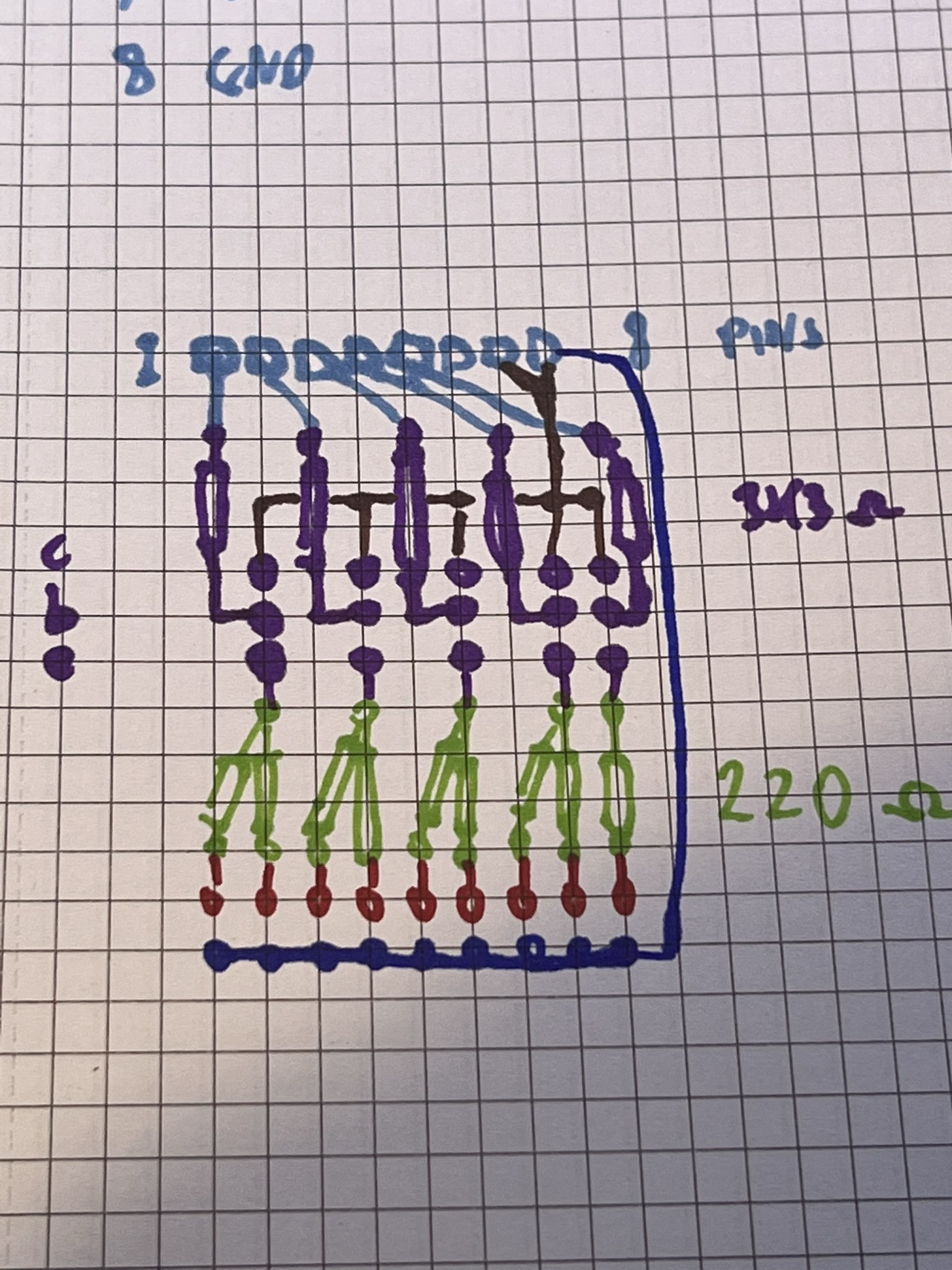
This is my rather crude sketch showing the PCB layout. At the top we have header pins for the 5 control inputs, and separate 5V and ground connections. Below that are 3K3 Ω base current bias resistors, and then (the purple dots) the 3 legs of 2N2222 transistors. With these the collectors and connected to the 5V supply and the emitters to the actual LED devices via 220 Ω current limiting resistors. The LEDs themselves are connected via thin wires from the PCB holes at the very bottom of the diagram.
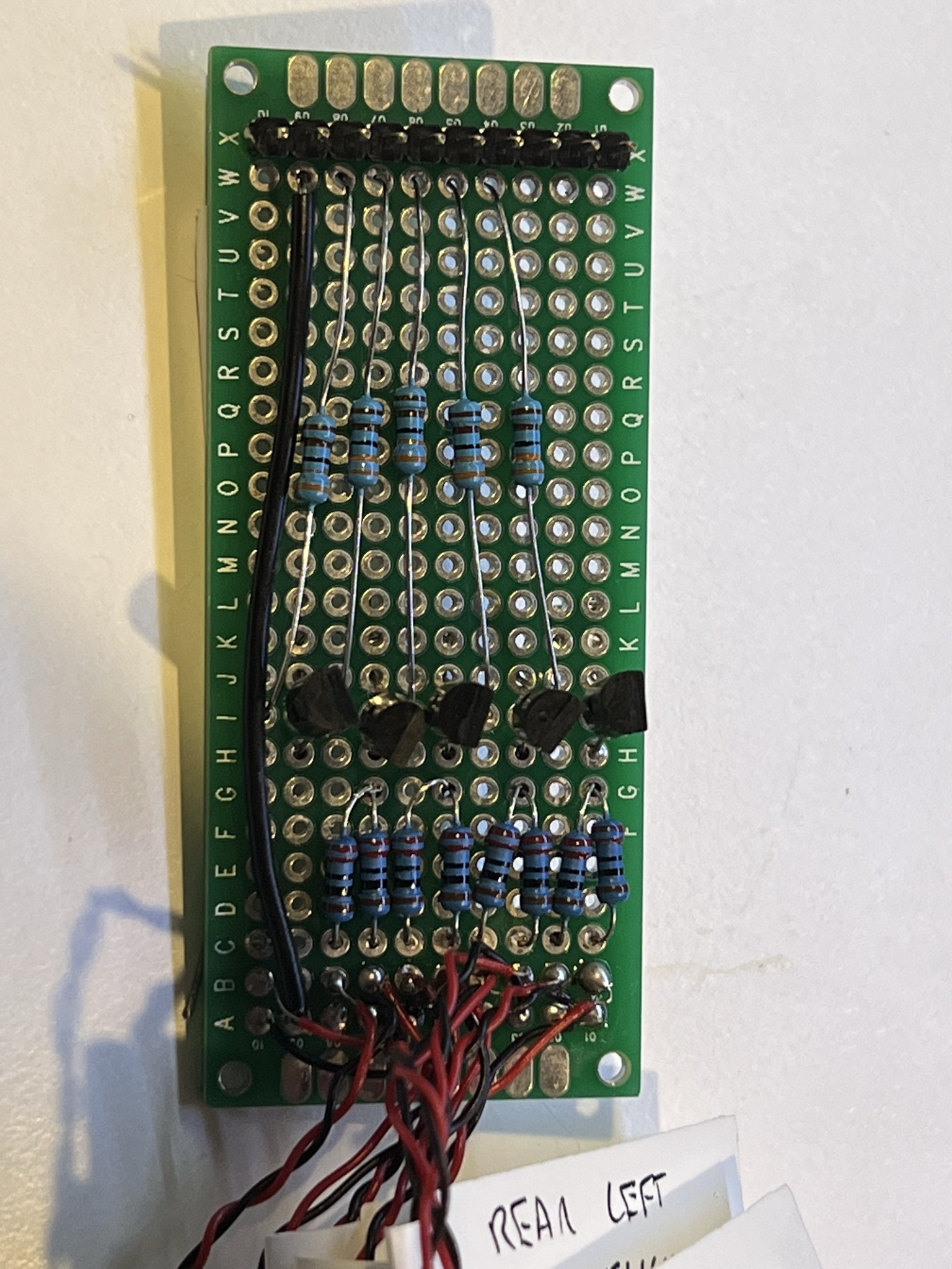
And this is the implementation, I could have shortenend the PCB a bit, but I wanted to leave a bit of room to add a micro USB input as an alternate source for the 5V and ground, and perhaps the trimpot to adjust the brightness, although my initial tests suggest it is fine and may not be needed.
The 10 LEDs require about 20mA of current each, which is a large chunk of that available if I were to drive them directly from an Arduino or Raspberry Pi, but thanks to the separate 5V supply and the transistors acting as switching amplifiers, the base current is only about 50 μA for each control input. Result!
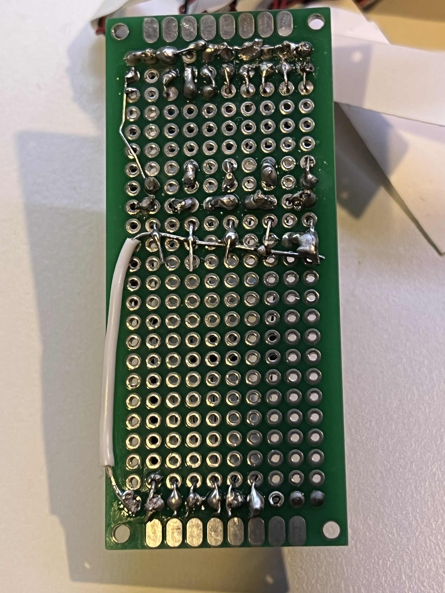
OK, I know the soldering is pretty awful, and even worse on the back side, but it does at least work and I promise I work harder to improve things here…
Next step, lets write some code to control the lights in my desired sequence….