Aims
To develop a “proof of concept” for the Raspberry Pi 400 Lego City controller by adding lights to the Lego City bus! We should be able to control each light group individually (headlights, tail-lights, indicators and an interior light), and there should be as little visible wiring as possible.
Challenges
Tiny LEDs are not actually a problem – pre-wired surface mount LEDs are available in quantity and in a variety of colours from Amazon or E-bay. We even have a choice to include a current limiting resistor in line if we want them. These LEDs are attached to pretty tiny (if rather short) wires already, so are ideal for squeezing between the bricks of a Lego contsruction.
Our first significant challenge is then three-fold:
- extending the short wires with further thin wire
- we probably need 30 to 40cm total length to get the wires away from visible areas
- Attaching thin wires to TTL logic
- In a way that is reliable but can be modified without soldering
- Providing more current than a GPIO output can support
- Probably not a real problem with a couple of SMD LEDs but lets assume that later we’ll have more devices to drive
Construction
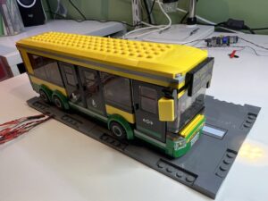
Incorporating tiny LEDs on tiny wires into Lego builds is fairly straight-forward. Perhaps best done during construction but not that hard even if we have an existing build. You can see the internal wires if you look hard enough but from a distance this looks untouched.
In this particular case we have added a Lego roadway and routed the combined wiring loom through the road surface for an even better effect. (Although the bus obviously no-longer moves – keep those hands off Kids!)
Wire Extension
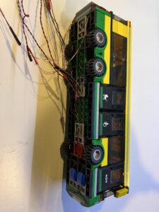
The purchased LEDs are attached to insulated wires about 10cm long but as noted above we need 30 to 40cm of thin wires to thread through Lego buildings to reach the “off stage” areas. For this purpose I’ve obtained a couple of reels of “wire-wrapping” wire which has a similar tiny gauge to the existing wires.
To join them I’ve just soldered the stripped ends side by side. I did try twisting them together but both a single strand and very fine so prone to break. Bringing the ends together along with the soldering iron and some solder is a bit fiddly and needs extra hands but forms a good joint.
The joint needs to be insulated, I’ve tried both very thin heat-shrink tubing and small pieces of electricians tape and both work fine, the tape is marginally quicker to do so I will probably stick with that.
Connecting to the TTL World
So we have some tiny wires but need to connect them to the 22 gauge, breadboard and Dupont connectors of hobbyist electronics world!
First attempt, direct attachment to Dupont connectors. A partial success – mostly worked but Dupont connections are crimped and sized for 22 gauge wire so the tabs on the crimps have to be squeezed very tightly to grip the thin wire-wrapping wire and even so is easily pulled out. Hmmm…
Second attempt, soldered to small circuit boards and held in place with hot glue. The small circuit boards can then have header pins attached, for onward connection via Dupont connectors. This approach has other advantages:
- We need current limiting resistors somewhere, so lets put them on this small circuit board
- We may also want to drive a greater current than a TTL output can provide, so:
- We can put driver transistors and base resistors on this board also
- Along with connections to a separate power supply
- And then what about a trim-pot on this supply to manage overall brightness?
- And we can combine outputs by a simple solder join if we are going to control them from a single input
- Or even build a network of header pins and use jumpers to map inputs to outputs…? (later maybe)